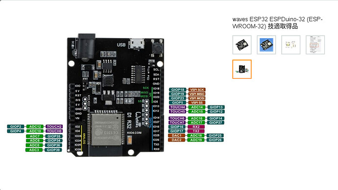
Pins SCK/CLK, SDO/SD0, SDI/SD1, SHD/SD2, SWP/SD3 and SCS/CMD, namely, GPIO6 to GPIO11 are connected to the integrated SPI flash integrated on the module and are not recommended for other uses.
Enable Input (ENABLE ). This input turns on or off all of the FET outputs. When set to a logic high, the outputs are disabled. When set to a logic low, the internal control enables the outputs as required. The translator inputs STEP, DIR, and MSx, as well as the internal sequencing logic, all remain active, independent of the ENABLE input state.
Note: All ESP32 I/O pins are 3.3V, not 5V tolerant, and the current capability is rather low. They cannot directly drive relays, solenoids, etc. In some cases they can directly drive optocouplers for external stepper drivers, but it is usually best to buffer them with an external chip or transistor. They can directly drive the control pins on “Pololu module” stepper drivers. You must not feed any 5V signals into an ESP32 input - limit switches and the like must use 3.3V signaling.
Google翻訳
注:すべてのESP32 I / Oピンは3.3Vであり、5Vトレラントではなく、電流容量はかなり低くなっています。リレーやソレノイドなどを直接駆動することはできません。外部ステッパードライバー用のオプトカプラーを直接駆動できる場合もありますが、通常は外部チップまたはトランジスタでバッファリングするのが最適です。 「Pololuモジュール」ステッピングドライバーの制御ピンを直接駆動できます。 5V信号をESP32入力に供給してはなりません。リミットスイッチなどは3.3V信号を使用する必要があります。
$4 の設定値
原文
By default, the stepper enable pin is high to disable and low to enable. If your setup needs the opposite, just invert the stepper enable pin by typing $4=1. Disable with $4=0. (May need a power cycle to load the change.)
You must select the Minimal SPIFFS (1.9MB APP with OTA/190KB SPIFFS) partition scheme under the Tools...Partition Scheme... menus, otherwise the firmware will not fit. との記載があるので、Minimal SPIFFS で行けるはずなのに上手く行きません。
※ Wiki によると、ESP32 では Bluetooth と Wifi は排他的であり、BT と WLAN の併用は出来無いそうです。
Example: **$Bluetooth/Name=ESP32_BT**. This would set the Bluetooth name to "ESP32_BT".
Put the radio mode into Bluetooth mode with the **$Radio/mode=BT**. The ESP32 uses the same hardware for Wifi and Bluetooth, so only one can be used at a time.
A reboot is required to change radio modes. Reboot the ESP32 to turn on Bluetooth with that name. You can reboot by power cycling, pushing the reset button on the ESP32 module or sending the **$System/Control=Restart** command.
Grbl Controller(BTシリアル)から
$SD/Status
$SD/List
$SD/Run=/test.gcode
※ コマンド
$SD/Status:Get SD Card Status
$SD/List:Get SD Card Content
$SD/Run:Print SD file
再びシリアルコンソール(USBシリアル)から
$Radio/Mode=AP
$System/Control=Restart
※ Mode
AP:AP for WiFi Access Point mode
STA:STA for WiFi station mode
BT:BT for Bluetooth
NONE:OFF
※ Wiki の記述で $SD/Run が $#D/Run と書かれている箇所がありますが、恐らくは打ち間違え。$SD/Run=/test.gcodeで問題なく通りました。
※ SDカードから動かす場合、gcode ファイルや ncファイルの書き方によっては読み込みに失敗するようです。単なる G コードの羅列であれば割と上手く行く感触です。