御指摘でだいぶ視界が開けて来ました。ありがとうございます。
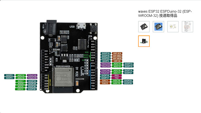
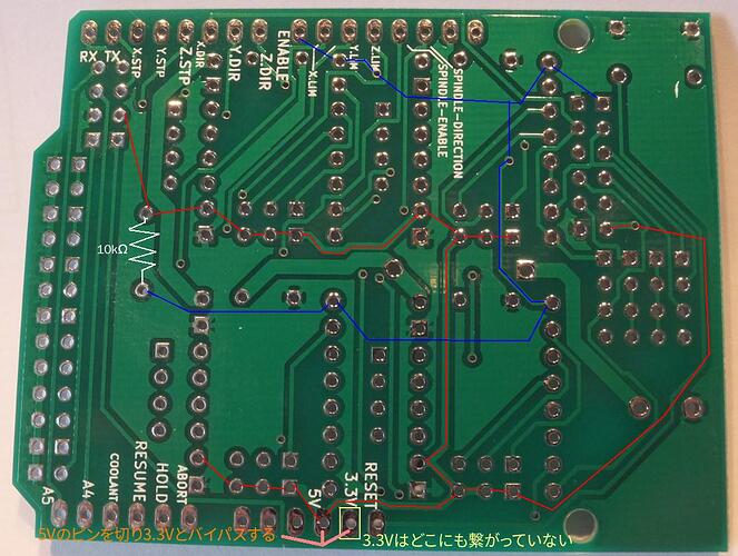
確認したところ、下のコード、 Grbl_ESP32 の Motors.cpp により IO12 が OUTPUT に指定されていました。ハイレベルの指定もこのあたりのコードから来ているものと思います。
    if (STEPPERS_DISABLE_PIN != UNDEFINED_PIN) {
        pinMode(STEPPERS_DISABLE_PIN, OUTPUT);  // global motor enable pin
        grbl_msg_sendf(CLIENT_SERIAL, MsgLevel::Info, "Global stepper disable pin:%s", pinName(STEPPERS_DISABLE_PIN));
    }
/*
	Motors.cpp
	Part of Grbl_ESP32
	2020 -	Bart Dring
	Grbl is free software: you can redistribute it and/or modify
	it under the terms of the GNU General Public License as published by
	the Free Software Foundation, either version 3 of the License, or
	(at your option) any later version.
	Grbl is distributed in the hope that it will be useful,
	but WITHOUT ANY WARRANTY; without even the implied warranty of
	MERCHANTABILITY or FITNESS FOR A PARTICULAR PURPOSE.  See the
	GNU General Public License for more details.
	You should have received a copy of the GNU General Public License
	along with Grbl.  If not, see <http://www.gnu.org/licenses/>.
	TODO
		Make sure public/private/protected is cleaned up.
		Only a few Unipolar axes have been setup in init()
		Get rid of Z_SERVO, just reply on Z_SERVO_PIN
		Class is ready to deal with non SPI pins, but they have not been needed yet.
			It would be nice in the config message though
オリジナルを表示
以下、問題を切り分けてみます。
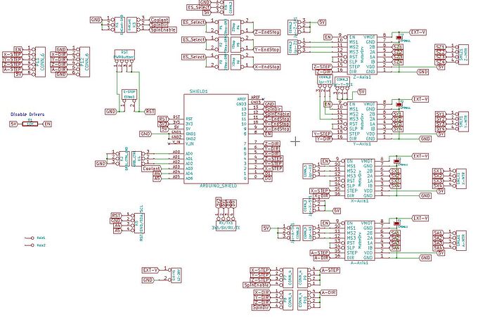
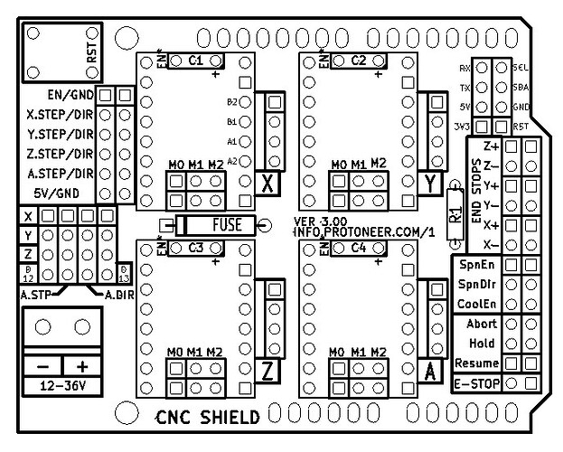
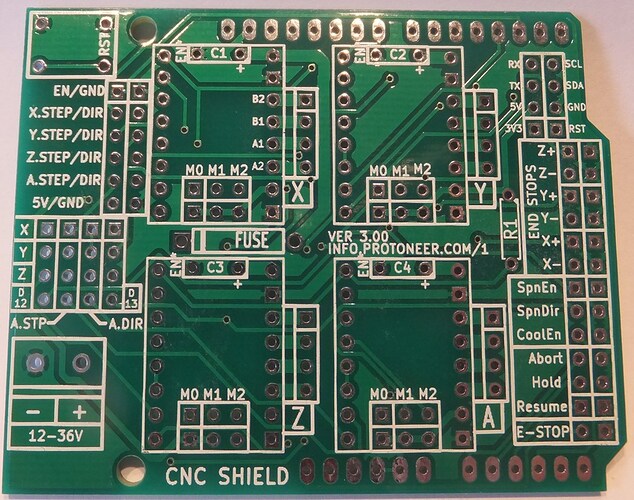
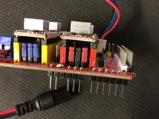
資料によっては EN/GND を短絡させ CNC Shield を有効化するとあるが、ここのジャンパは本来 Shield 自身の有効無効切り替え用ではない模様。
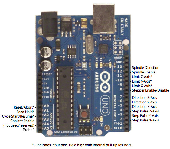
EN/GND のショートは用いず、Grbl/Grbl_ESP32 側で Stepper Enable/Disable PIN(Shield 無改造の場合 IO12)の High Low を切り替えて Stepper Driver の Enable/Disable を切り換えるのが本来の運用と思われる。
Grbl_ESP32 のステッピングモータドライバの使われ方として、「モータ動作時間+遅延時間」分だけ Enable が入り、普段は Disable。
シリアルコマンドでは $1 や $4 や $SLP が、Gコードでは M17 や M18 や M84 がこれに関係。
Motors.cpp から推測し、Grbl_ESP32 のスケッチのコンパイル時、src/Machines 配下のヘッダファイルで STEPPERS ENABLE/DISABLE PIN に IO12 等のいずれかのIOを割り当てなければここは UNDEFINED_PIN となり High にならない⇒ステッパードライバ常時 ON と予想する。
※ ドキュメントやヘッダファイルに記載がないので、Grbl では M17,M18,M84 は使わないのかもしれません。
※ $SLP ⇒ Grbl v1.1 Commands · gnea/grbl Wiki · GitHub
M17:全てのステッパーモーターの電源を入れる
This command can be used to enable one or more steppers (X,Y,Z,A,B,C,U,V,W,E).
M18:全てのステッパーモーターの電源をオフ or 回転をオフ
This command can be used to set the stepper inactivity timeout (S) or to disable one or more steppers (X,Y,Z,A,B,C,U,V,W,E).
G-code (abbreviation for geometric code; also called RS-274, standardized today in ISO 6983-1) is the most widely used computer numerical control (CNC) and 3D printing programming language. It is used mainly in computer-aided manufacturing to control automated machine tools, as well as for 3D-printer slicer applications. G-code has many variants.
G-code instructions are provided to a machine controller (industrial computer) that tells the motors where to move, how fast to move, and what path to ...
↓モータドライバの Enable/Disable 切り替えについての議論
オープン 09:52PM - 28 Aug 16 UTC
閉鎖 01:03AM - 05 Mar 18 UTC
It would be great if these two commands (M17/M18) could be implemented in GRBL s… uch that M17 enables power to the stepper motors, and M18 disables power to the stepper motors.
I know that current by using $1=255 one can enable/disable the steppers after a move, but a pure g-code solution would be excellent. Possibly a configuration option to set the maximum time to keep steppers enabled (say 1 minute) could be introduced so that the steppers can't be left on (leading to them being worn out) for longer than the time it takes for someone to do a manual tool change.
オープン 12:29PM - 17 Sep 17 UTC
閉鎖 01:00PM - 22 Sep 17 UTC
I've noticed people talking about using M18 on some machines to stop all motors … so that no current is present and they can be moved freely. Can GRBL do it with a different command because M18 is not recognised as a valid command.
Thanks.
OUTPUT に指定されていました。
    if (STEPPERS_DISABLE_PIN != UNDEFINED_PIN) {
        pinMode(STEPPERS_DISABLE_PIN, OUTPUT);  // global motor enable pin
        grbl_msg_sendf(CLIENT_SERIAL, MsgLevel::Info, "Global stepper disable pin:%s", pinName(STEPPERS_DISABLE_PIN));
    }
/*
	Motors.cpp
	Part of Grbl_ESP32
	2020 -	Bart Dring
	Grbl is free software: you can redistribute it and/or modify
	it under the terms of the GNU General Public License as published by
	the Free Software Foundation, either version 3 of the License, or
	(at your option) any later version.
	Grbl is distributed in the hope that it will be useful,
	but WITHOUT ANY WARRANTY; without even the implied warranty of
	MERCHANTABILITY or FITNESS FOR A PARTICULAR PURPOSE.  See the
	GNU General Public License for more details.
	You should have received a copy of the GNU General Public License
	along with Grbl.  If not, see <http://www.gnu.org/licenses/>.
	TODO
		Make sure public/private/protected is cleaned up.
		Only a few Unipolar axes have been setup in init()
		Get rid of Z_SERVO, just reply on Z_SERVO_PIN
		Class is ready to deal with non SPI pins, but they have not been needed yet.
			It would be nice in the config message though
オリジナルを表示
使われないピンには UNDEFINED_PIN が割り当てられるようです。
#pragma once

#include <Arduino.h>

const int UNDEFINED_PIN    = 255;  // Can be used to show a pin has no i/O assigned
const int I2S_OUT_PIN_BASE = 128;

extern "C" int  __digitalRead(uint8_t pin);
extern "C" void __pinMode(uint8_t pin, uint8_t mode);
extern "C" void __digitalWrite(uint8_t pin, uint8_t val);

String pinName(uint8_t pin);
#pragma once

/*
    UserOutput.h

    Part of Grbl_ESP32

    2020 -	Bart Dring

    Grbl is free software: you can redistribute it and/or modify
    it under the terms of the GNU General Public License as published by
    the Free Software Foundation, either version 3 of the License, or
    (at your option) any later version.
    Grbl is distributed in the hope that it will be useful,
    but WITHOUT ANY WARRANTY; without even the implied warranty of
    MERCHANTABILITY or FITNESS FOR A PARTICULAR PURPOSE.  See the
    GNU General Public License for more details.
    You should have received a copy of the GNU General Public License
    along with Grbl.  If not, see <http://www.gnu.org/licenses/>.
*/
オリジナルを表示
https://www.arduino.cc/reference/en/language/functions/digital-io/pinmode/
http://www.musashinodenpa.com/arduino/ref/index.php?f=0&pos=2014
https://www.arduino.cc/en/Tutorial/Foundations/DigitalPins
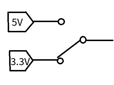
Note: All ESP32 I/O pins are 3.3V, not 5V tolerant, and the current capability is rather low. They cannot directly drive relays, solenoids, etc. In some cases they can directly drive optocouplers for external stepper drivers, but it is usually best to buffer them with an external chip or transistor. They can directly drive the control pins on “Pololu module” stepper drivers. You must not feed any 5V signals into an ESP32 input - limit switches and the like must use 3.3V signaling.
注:すべてのESP32 I / Oピンは3.3Vであり、5Vトレラントではなく、電流容量はかなり低くなっています。リレーやソレノイドなどを直接駆動することはできません。外部ステッパードライバー用のオプトカプラーを直接駆動できる場合もありますが、通常は外部チップまたはトランジスタでバッファリングするのが最適です。 「Pololuモジュール」ステッピングドライバーの制御ピンを直接駆動できます。 5V信号をESP32入力に供給してはなりません。リミットスイッチなどは3.3V信号を使用する必要があります。
By default, the stepper enable pin is high to disable and low to enable. If your setup needs the opposite, just invert the stepper enable pin by typing $4=1. Disable with $4=0. (May need a power cycle to load the change.)
デフォルトでは、ステッパーイネーブルピンは無効の場合はハイ、有効の場合はローです。セットアップで反対のことが必要な場合は、$ 4 = 1と入力してステッパーイネーブルピンを反転します。 $ 4 = 0で無効にします。 (変更をロードするには、電源を入れ直す必要がある場合があります。)
以下の参考文献を読むまでは思い至りませんでしたが、機能の必要性としては、ステッパードライバの「発熱対策」「ノイズ対策」「消費電力対策」があるようです。Stepper Enable/Disable Pin の出力が、指定された「ディレイタイム」を過ぎると High⇒Disable となり、CNC 作動時は Low⇒Enable となることで必要な時間のみ動かし、発熱やノイズ、電力消費を抑制する仕組みであると想像します。
Grbl_ESP32 の場合、$1=255 を指定することでディレイのかわりに「電力を消費しながら現在の状態で停止し続け させる」ことが出来るそうです。
加えて、$SLP コマンドによりステッパードライバを Disable にしてモーターを空回りする状態にも変更可能とのことです。
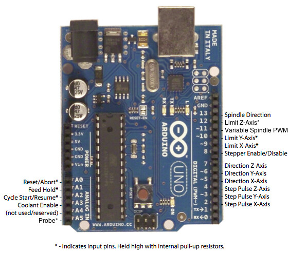
![]() ESPDuino で CNC Shield を利用される際は、念の為 Analog Input がシルク印刷通りか確認することをおすすめします
ESPDuino で CNC Shield を利用される際は、念の為 Analog Input がシルク印刷通りか確認することをおすすめします ![]()


